The story behind
Magnetometer kit


We took it one step further…
Speake sensors business closed…

Electronics boards


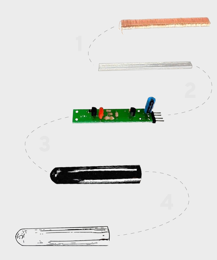
Inside the process…
FGM 3 PRO Sensor Cutout


Photos from our ready made magnetometer kits


A walk inside the laboratory…
Inside the process…

Building a gradiometer kit…
Also, as 2 magnetic field sensors are required as a pair to build a gradiometer kit, their electric properties must be equally balanced for both sensors. In the original FGM sensor design and various web site offered FGM imitations the matching procedures for every pair were not implemented. We are dedicated to match every pair of magnetometer sensors produced so that their voltage outputs will be exactly the same.
Therefore the gradiometer kit you receive will only have to be adjusted by aligning the sensors (for canceling the earth magnetic field as you will read in the pdf), and not any interference signal occurs from a pair where one magnetic field sensor has a different signal output compared to the other. The sensor pair matching enables you to align the sensors easier and faster as it has minimized false magnetometer signal effects.


FGM 3 PRO gradiometer sensors are matched in pairs with equal electronic properties?
The signal output on every individual FGM 3 PRO sensor has been tested in our lab and marked by hand on its label. To construct a reliable gradiometer both sensors have to produce exactly the same signal output, otherwise noise and unstable operation occurs. The pair of gradiometer sensors you will receive has been selected so that both sensors are matched to produce exactly the same signal output. In other words, every pair has the same linearity, and the end result is great depth performance. The output of each sensor is marked outside and matches to the sensor that it has been paired with.
Positioning the sensors


